A modern DC fast charger may look like a simple cabinet from the outside, but internally it is a sophisticated power-conversion system.
The charger receives three-phase AC electricity from the electrical grid and converts it into controlled DC power suitable for an electric vehicle battery.
The major stages involved in this conversion include input protection, EMI filtering, rectification, power-factor correction, the DC link, power modules, DC-DC conversion, output filtering and the CCS2 charging interface.
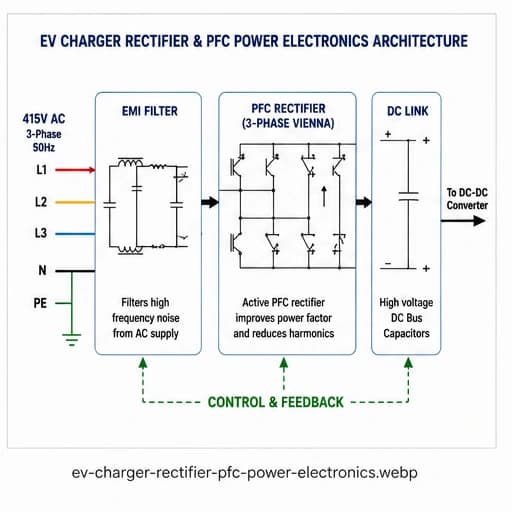
Simplified AC-to-DC power conversion architecture used in a DC fast charger.
What Does a Rectifier Do in an EV Charger?
A rectifier converts alternating current (AC) into direct current (DC). This is one of the fundamental power-conversion stages inside a DC fast charger.
The electrical grid supplies AC power, while the high-voltage battery inside an electric vehicle requires DC power. The rectifier therefore forms the first major conversion stage between the grid and the vehicle battery.
THREE-PHASE AC GRID
        │
        ▼
   EMI FILTER
        │
        ▼
 PFC / RECTIFIER
        │
        ▼
     DC LINK
        │
        ▼
   POWER MODULES
        │
        ▼
    DC-DC STAGE
        │
        ▼
      CCS2
        │
        ▼
    EV BATTERY
Why Is PFC Used in DC Fast Chargers?
PFC stands for Power Factor Correction. The PFC stage controls the relationship between the voltage and current drawn from the AC supply.
In high-power EV charging systems, power-factor correction is important for efficient use of the electrical supply and for controlling the input current waveform.
AC Input
Three-phase AC power is supplied from the electrical distribution system.
PFC / Rectifier
The AC input is converted into a controlled DC supply while managing the input current.
DC Link
The resulting high-voltage DC provides the intermediate energy bus for downstream power conversion.
What Is an EV Charger Power Module?
A power module is a modular power-conversion building block used inside many commercial DC fast chargers.
Instead of designing one extremely large converter, manufacturers can use multiple power-conversion modules working together to achieve the required charger power.
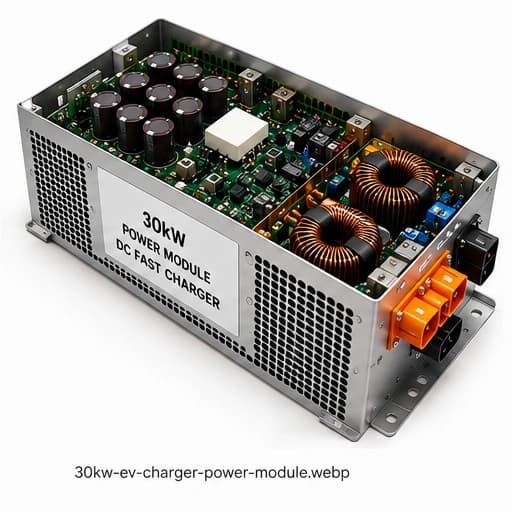
Illustrative 30kW-class power module used as a building block in modular DC fast-charging architectures.
Modular Power Architecture
Modular power conversion makes it possible to scale charger capacity by combining multiple power-conversion units.
For example, a charger using 30kW-class modules could theoretically be arranged as follows:
The above is an illustrative modular scaling example based on 30kW-class modules. Actual charger architectures, module ratings, redundancy and power-sharing arrangements vary by manufacturer.
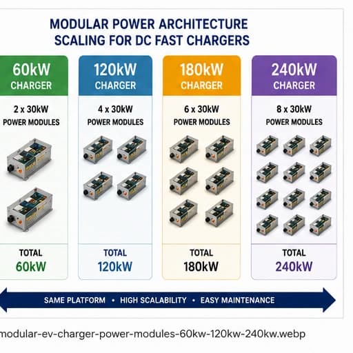
Illustrative modular scaling concept for higher-power DC fast chargers.
60kW DC Fast Charger Architecture
A 60kW DC fast charger can use multiple power-conversion modules whose combined capacity provides the required output power.
                 3-PHASE AC
                       │
                       ▼
                 EMI / FILTER
                       │
                       ▼
                  PFC RECTIFIER
                       │
                       ▼
                    DC LINK
                       │
              ┌────────┴────────┐
              │                 │
              ▼                 ▼
         POWER MODULE       POWER MODULE
           ~30kW              ~30kW
              │                 │
              └────────┬────────┘
                       │
                       ▼
                   DC OUTPUT
                       │
                       ▼
                     CCS2
                       │
                       ▼
                  EV BATTERY
120kW DC Fast Charger Architecture
A 120kW charger can use a larger modular power-conversion system. For example, four 30kW-class modules provide a nominal combined module capacity of 120kW.
                  AC GRID
                      │
                      ▼
                PFC / RECTIFIER
                      │
                      ▼
                   DC LINK
                      │
         ┌────────────┼────────────┐
         │            │            │
         ▼            ▼            ▼
       30kW         30kW         30kW
       MODULE       MODULE       MODULE
         │            │            │
         └────────────┴──────┬─────┘
                             │
                           30kW
                           MODULE
                             │
                             ▼
                            120kW
                             │
                             ▼
                            CCS2
What Does the DC-DC Converter Do?
The DC-DC conversion stage regulates the DC voltage and current delivered to the vehicle.
EV batteries can operate over a wide voltage range. Therefore, the charger needs controlled power conversion between the internal DC bus and the vehicle-side DC output.
DC LINK
   │
   ▼
HIGH-FREQUENCY
SWITCHING STAGE
   │
   ▼
DC-DC CONVERTER
   │
   ▼
OUTPUT FILTER
   │
   ▼
CCS2 CONNECTOR
   │
   ▼
EV BATTERY
SiC MOSFETs in EV Charger Power Electronics
Silicon Carbide, commonly abbreviated as SiC, is a semiconductor material used in modern high-power switching applications.
SiC MOSFETs can support high-frequency switching and can enable high power density and efficient power conversion when appropriately designed and controlled.
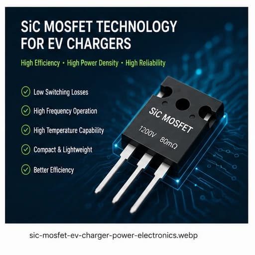
Illustrative SiC MOSFET power semiconductor technology used in high-efficiency power conversion.
High switching frequency
High power density
High-temperature capability
Efficient power conversion
What Is Inside a DC Fast Charger?
A commercial DC fast charger contains considerably more than the charging connector and display.
Depending on the manufacturer and charger design, the cabinet can contain power modules, contactors, fuses, DC-link capacitors, control electronics, current and voltage sensors, communication electronics and thermal-management systems.
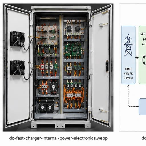
Internal electrical and power-electronics arrangement of a DC fast charger cabinet.
Complete DC Fast Charger Internal Architecture
The complete power path can be simplified into the following architecture:
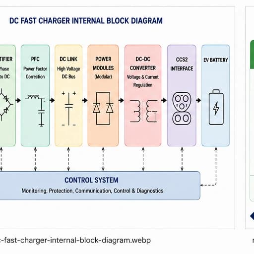
Simplified internal power architecture of a DC fast charger.
GRID
 │
 ▼
INPUT PROTECTION
 │
 ▼
EMI FILTER
 │
 ▼
RECTIFIER / PFC
 │
 ▼
DC LINK
 │
 ▼
POWER MODULES
 │
 ▼
DC-DC CONVERSION
 │
 ▼
OUTPUT FILTER
 │
 ▼
CCS2
 │
 ▼
EV BATTERY
Why Thermal Management Matters
Power conversion is not completely lossless. A portion of the input electrical energy is dissipated as heat inside semiconductor switches, magnetic components, conductors and other components.
Thermal management therefore becomes increasingly important as charger power increases.
ELECTRICAL POWER
       │
       ▼
POWER ELECTRONICS
       │
       ├──────────────► USEFUL DC POWER
       │
       └──────────────► CONVERSION LOSSES
                              │
                              ▼
                             HEAT
                              │
                              ▼
                           COOLING
From the Grid to the EV Battery
In simple terms, the charger performs a sequence of power conversions:
Grid
Three-phase AC electrical supply
Rectifier
AC is converted into DC
PFC
Input current and power factor are controlled
DC Link
Intermediate high-voltage DC bus
Power Modules
Modular high-power conversion
DC-DC
Output voltage and current regulation
CCS2
Controlled DC power delivered to the vehicle
EV Battery
Battery receives DC charging power
Engineering Note
The exact internal semiconductor topology, power-module arrangement and control architecture of a particular charger's manufacturer may be proprietary. The diagrams in this article therefore represent general engineering architectures and should not be interpreted as an exact reconstruction of a specific certified charger's internal circuit unless supported by the manufacturer's technical documentation.
Share This Article
Altarbyte
Turnkey EV Charging Infrastructure
DC fast chargers are only one part of a complete EV charging hub. A reliable charging installation also requires appropriate electrical infrastructure, transformer capacity, HT/LT distribution, protection, civil works, earthing, communication systems and commissioning.
Talk to Altarbyte